Joysticks
For
The Commodore 64
Michael A. Tyborski
The Commodore 64
Michael A. Tyborski
The Commodore 64 is, among other things, an excellent game machine. It features advanced graphics, realistic sound, joysticks, and paddles. Learning how to use the joysticks is one of the first steps toward making full use of your 64's entertainment capabilities.
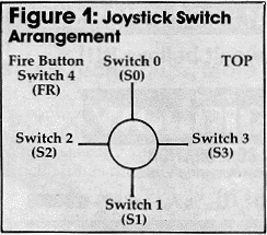
The Commodore/Atari joystick is a very simple device consisting of four switches, as shown in Figure 1. When the control handle is moved, one or two switches close in various combinations. This provides an easy way to detect the joystick's position. There is also an independent switch called the fire button. It can be used to fire lasers, drop bombs, and select options.
How To Read Positions
Each joystick connects to a port on a 6526 "Complex Interface Adapter" (CIA). The back joystick uses port A, and the other uses port B. These ports are at addresses 56320 and 56321 respectively. This makes joystick selection extremely simple.
Since both ports (like those on the VIC) are also part of the keyboard scanning matrix, simultaneous use of the keyboard and joysticks is prevented. Fortunately, this is a minor problem.
The direction switches connect to port bits 0-3, but the ports return a value from 0-255 decimal when read. As a result, you should AND this value with 15 when reading the joystick direction.
Similarly, the fire buttons connect to bit 4 on the ports. To read them, AND the port value with 16. This returns zero when the button is pressed, and 16 otherwise.
For example, you can quickly test the back joystick with this program:
10 PRINT
PEEK(56320)AND15,-((PEEK(56320)
AND16)=16)
20 GOTO 10
AND16)=16)
20 GOTO 10
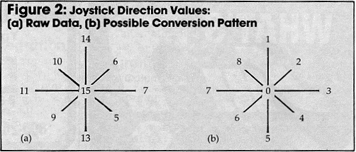
You will read values like those in Figure 2a. Although usable, they are awkward to work with.
A better program would return easy-to-use direction codes. This would require more time, but it would simplify other programming. Figure 2b shows one possible pattern. The sequential values allow an ON-GOTO or ON-GOSUB statement to control program flow.


Joystick Read Subroutine
Now, let's tie all this together. The program below shows the necessary statements to read the 64 joystick. First, we will need to initialize a conversion array. We do this in a short initialization subroutine (lines 9000-9040). The routine also sets up the system constants: PA, JM, and FM.
Variable PA holds the joystick port base address; variables JM and FM are masks for future AND operations. These variables speed up the joystick read subroutine by eliminating floating point conversions. This is important for smooth graphic control.
The joystick read subroutine (lines 1000-1040) performs the real work. It reads the status of the joystick selected by variable SN. It then sets variable JV to a direction code as shown in Figure 2b and tests the fire button. If the fire button is pressed, it sets variable FB to one.
The subroutine documentation explains the calling procedure. And more important, it shows which variables are reserved for joystick use.
You should eliminate the REMark statements when using lines 1000-1040. In addition, place them at the beginning of your program and the initialization routine at the end. This will speed things up a bit.
1000 REM JOYSTICK READ ROUTINE
1010 SN=SN AND 1:JS=PEEK(PA+SN):JV=JS
AND JM
1020 FOR JI=1 TO 8:IF JV=JV(JI) THEN
1040
1030 NEXT:JI=0
1040 JV=JI:FB=-((JS AND FM)=ZR):RETURN
9000 REM INITIALIZATION SUBROUTINE
9010 PA=56320:JM=15:FM=16:ZR=0
9020 FOR JI=1 TO 8:READ JV(JI):NEXT
9030 DATA 14,6,7,5,13,9,11,10
9040 RETURN