by Tom Hudson
Welcome back! As I mentioned last issue, there are only a few more 6502 instructions left for us to cover, and we'll talk about them in the next two installments. There are also a couple of instructions we're going to skip until later. They are for more advanced uses and won't make much sense until you've got more experience with assembly language.
Several people have written lately, asking if we'll get into full-scale programs using the Atari's powerful operating system. The answer: You bet! We're going to find out how to access the disk, cassette, graphics, keyboard and just about anything else you'd like to hear about. We'll study routines for high-speed math, player/missile graphics and more. Boot Camp is here not only to teach you what 6502 assembly instructions do, but how to apply them.
TWO
Solutions
Last issue, I asked you to write a program that
multiplied the number 5 by 27. There are an almost infinite number of
ways to do this, and I'll show you two of them now. Remember, these
aren't the only possibilities, and even though your solution may not be
as efficient, getting the correct answer is what counts most.| 10 *= $600 20 CLD ;BINARY MATH! 30 LDA #5 ;GET # TO MULT. 40 STA TIMES1 ;SAVE # TIMES 1 50 ASL A ;*2 60 STA TIMES2 ;SAVE # TIMES 2 70 ASL A ;*4 80 ASL A ;*8 50 STA TIMES8 ;SAVE # TIMES 8 0100 ASL A ;*16 0110 CLC ;CLEAR FOR ADD 0120 ADC TIMES8 ;*24 0130 CLC ;CLEAR AGAIN 0140 ADC TIMES2 ;*26 0150 CLC ;CLEAR AGAIN 0160 ADC TIMES1 ;*27 0170 STA RESULT ;SAVE # TIMES 7 0180 BRK ;WE'RE DONE! 0190 TIMES1 *=*+1 0200 TIMES2 *=*+1 0210 TIMES8 *=*+1 0220 RESULT *=*+1 0230 .END |
The first solution I'm going to cover is shown above. This program uses the principle of breaking a multiply into bite-sized pieces, as shown last issue. In this case, I broke the multiply by 27 down into the following group of adds:
|
(number
* 16)
(number
* 8)
(number
* 2)
(number
)
-------------
(number * 27)
|
Let's step through the program and see how it works.
Line 20-clears the decimal mode. Always remember to be sure of the setting of the decimal flag before doing any arithmetic.
Line 30-loads the accumulator with the number 5. When the routine is finished, this number will be multiplied by 27 and stored in the memory location labeled RESULT.
Line 40-stores the accumulator's contents in the memory location labeled TIMES1 (5*1). We need to save this value for later, when we add the bite-sized pieces together.
Line 50-shifts the accumulator contents left one bit, multiplying it by two.
Line 60-saves the accumulator (now 5*2) in the location TIMES2. This value is also needed for our final result.
Line 70-shifts the accumulator left one bit again, leaving the accumulator with the value 5*4.
Line 80-performs another left shift on the accumulator. The accumulator now contains 5*8.
Line 90-saves the accumulator's contents in the location TIMES8.
Line 100-performs a final left shift on the accumulator, leaving the accumulator with the value 5*16. At this point, we have all the bite-sized pieces we need to get our answer and are ready to add them up.
Line 110-clears the carry flag for the first add in the group. Remember, this is a necessary instruction before any single-byte addition.
Line 120-adds the accumulator (5*16) to TIMES8 (5*8), leaving the result (5*24) in the accumulator for the next add.
Line 130-clears the carry for the next add.
Line 140-adds the accumulator (5*24) to TIMES2 (5*27), with the result (5*26) left in the accumulator.
Line 150-clears the carry again, for the final addition operation.
Line 160-adds the accumulator (5*26) to TIMES1 (5*1), leaving the accumulator holding the final value, 5 times 27!
Line 170-saves the final answer in the location labeled RESULT.
Line 180-BREAKs the execution of the program. At this point, you can check the location RESULT to be sure it contains 5*27, or 135 ($87 hex).
Lines 190-220-reserve one byte for each of the four data areas used by the program.
| Solutioin -2. |
The second solution is a modification of the first technique. In this program, I break the multiply down into smaller pieces again, but structure it so that subtracts are used instead of adds:
|
(number * 32)
(number * 4)
-
(number )
------------- (number * 27) |
As you can see, we get the same result as with adds, but with only three math operations instead of four. The figure below shows the 6502 code necessary to implement this method.
| 10 *= $0600 20 CLD ;BINARY MATH 30 LDA #5 ;GET # TO MULT. 40 STA TIMES1 ;SAVE # TIMES 1 50 ASL A ;*2 60 ASL A ;*4 70 STA TIMES4 ;SAVE # TIMES 4 80 ALS A ;*8 90 ASL A ;*16 0100 ASL A ;*32 0110 SEC ;SET FOR SUBTRACT 0120 SBC TIMES4 ;*28 0130 SEC ;SET AGAIN 0140 SBC TIMES1 ;*27 0150 STA RESULT ;SAVE # TIMES 27 0160 BRK ;ALL DONE! 0170 TIMES1 *=*+1 0180 TIMES4 *=*+1 0190 RESULT *=*+1 0200 .END |
Let's walk through this program and see what's going on.
Line 20-clears the decimal mode for binary arithmetic. I can't overemphasize the importance of knowing the status of the decimal mode flag. If you're in doubt, set or clear it as needed.
Line 30-loads the accumulator with the number 5. When this program is finished, the number 5 will be multiplied by 27.
Line 40-saves the contents of the accumulator in the location labeled TIMES1, for later use.
Line 50-shifts the accumulator left one bit, multiplying it by 2.
Line 60-shifts the accumulator left again, leaving the accumulator with the value 5*4.
Line 70-saves the contents of the accumulator (5*4) in the memory location TIMES4.
Line 80-shifts the accumulator left again, leaving the value 5*8 in the accumulator.
Line 90-performs another left shift. At this point the accumulator contains 5*16.
Line 100-shifts the accumulator left a final time. The accumulator now contains the value 5*32. We are now ready to perform the subtract operations as shown above.
Line 110-sets the carry flag for the first subtract operation. Remember, the carry flag should always be set before a single-byte subtract to ensure correct results.
Line 120-subtracts the value TIMES4 (5*4) from the accumulator (5*32), leaving the accumulator containing the value 5*28.
Line 130-sets the carry flag for the next subtract.
Line 140-subtracts the value TIMES1 (5*1) from the accumulator (5*28), leaving the accumulator with the value 5*27!
Line 150-saves the answer in the location labeled RESULT.
Line 160-stops the program's execution with the BRK instruction. At this point, you can verify that the location RESULT (and the accumulator) contains 5*27, or 135 ($87 hex).
Lines 170-190-reserve one byte for each of the three data fields used by the program.
Obviously, these are just two of the thousands of solutions possible for this problem.
Stacking
the Deck
The last topic we're going to cover before going on
to bigger and better things is the 6502 stack. This is an important
feature of the 6502, as it allows us to write subroutines. Since the
stack concept is important, we're going to cover it in detail starting
with this issue and finish it with assembly examples next time. Let's
get started finding out what the stack is and how it works.The 6502 reserves 256 bytes of memory from $0100-01FF (also called page 1) for a temporary storage area. We call this area the stack. This area is automatically maintained for the 6502, but we can use it for short-term storage, too.
We call the stack a "last-in, first-out" structure. The last number placed on the stack is always the first to be pulled off. A good way to remember this is to think of a stack of pancakes. When you pile them up, the last one put on the stack is on top. When you take them off one at a time, the last one you put on comes off first. Using this analogy, the computer could keep track of 256 pancakes, each with a number written on it.
The computer keeps track of the stack's contents by using the Stack Pointer register inside the 6502. This pointer ranges from $00-FF When the stack pointer contains $00, it is pointing to the memory location $0100. When it contains $FF, the location $01FF is indicated.
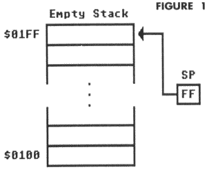
Interestingly, the stack works backwards from the way we would expect. When the stack is empty, the stack pointer is set to $FF. Figure 1 shows an empty stack.

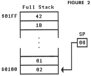
As the stack is filled with more and more values, the stack pointer is decremented, pointing to lower areas of page 1. When completely filled, the stack pointer will contain $00, as shown in Figure 2.

Since the computer has only reserved 256 bytes for a stack, there are obviously limitations in its use. If the stack is filled with too many values, the stack pointer will wrap around back to $FF and begin wiping out earlier stack entries! There is no error message for this, so you must be careful when working with the stack.
When entries are removed from the stack, the process is reversed. As each byte is pulled off the stack, the pointer is incremented, pointing to progressively higher locations of the stack.
How
Subroutines Work
In BASIC, subroutines are easy to write. You simply
set up the necessary BASIC code, put a RETURN instruction at the end of
it, and call it with the GOSUB statement whenever you need it. The
subroutine code is performed, and BASIC resumes execution at the next
statement after the GOSUB. Neat, huh?In order for a BASIC subroutine to work, the computer has to know how to get back to the instruction after the GOSUB. It does this by using a stack. Let's look at a simplified example of how a BASIC subroutine is executed.
|
10 GOSUB 100
20 END
100 GOSUB 200
110 RETURN
200 A=A+1
210
RETURN
|
The above is a short BASIC program using the BASIC subroutine statements, GOSUB and RETURN. We're going to step through it and watch what happens to the BASIC stack, a special area similar to the 6502 stack.
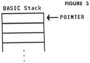
Before execution, the stack is empty, and the stack pointer is pointing to the first available position.

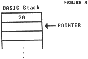
Line 10-GOSUB to Line 100 is executed. First, the computer finds the next statement after GOSUB. The next statement is in Line 20, so the computer pushes that line number onto the first location on the stack, and changes the stack pointer to point to the next available location. Execution then proceeds at Line 100. At this point, the stack looks like:

Line 100-This line executes a GOSUB to Line 200. The next statement after this GOSUB is Line 110, so this number is placed on the stack, and the stack pointer is advanced to the next available position. Execution continues at Line 200. The stack now looks like:

Line 200-The computer adds one to the variable A. The stack is not affected.
Line 210-The computer encounters a RETURN statement. At this point, the computer increments the stack pointer, like so:

Now the computer takes the line number 110 from the stack. As you can see, the computer can now go back to the instruction after the last GOSUB. Execution continues at Line 110.
Line 110-Another RETURN is encountered, and the stack pointer is incremented again. Now the stack looks like this:

The computer gets the line number from the stack and completes the RETURN by resuming execution at Line 20.
Line 20-This line terminates execution with the END statement. The stack is back to its original condition, with the pointer indicating the first stack location. The line numbers are still in the stack itself, but since the stack pointer no longer points to them, they are no longer active. They will be wiped out by new stack entries.
Now do you see how the stack works? It's a great way to handle subroutines, where the computer must be able to find its way back to the code which called up the subroutine.
Until
Next Time
If you think Boot Camp looks more like BASIC
Training this issue, hold on! I wanted to explain the subroutine
process in a language you're familiar with, like BASIC. Next issue
we'll examine the operation of the 6502 subroutine process and learn
how to use the stack for our own programs.10
GOSUB 10
29 END
29 END
Until we meet again, the above is a little program to get you thinking. Type in the BASIC program and run it. It may take a while, but something will happen, and I want you to see if you can find the cause. Use the stack illustration method I used in the BASIC example to get the answer.
Also, if you haven't already, try to find more alternate methods for multiplying five by 27!
